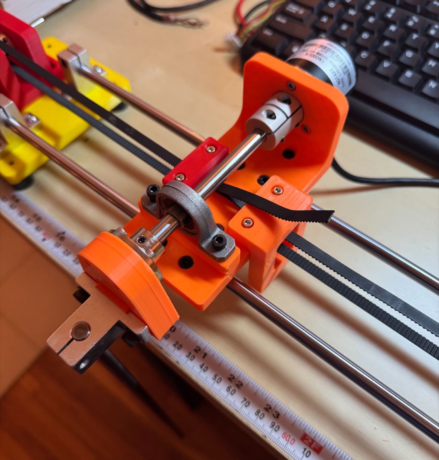
Inverted Pendulum
A self-balancing pendulum controlled with a real-time PID loop.
Goals
- Explore control systems: build a practical understanding of PID feedback loops.
- Combine mechanical design, electrical prototyping, and programming into one working system.
- Implement real-time control on an Arduino UNO.
How it works
The pendulum spins on a shaft mounted to a carriage, and balances by moving that carriage in the direction the pendulum is falling. A PID controller sets the carriage's speed and direction, using the pendulum's angle as its input. An encoder mounted to the carriage, fixed to the same shaft the pendulum spins on, tracks that angle in real time.
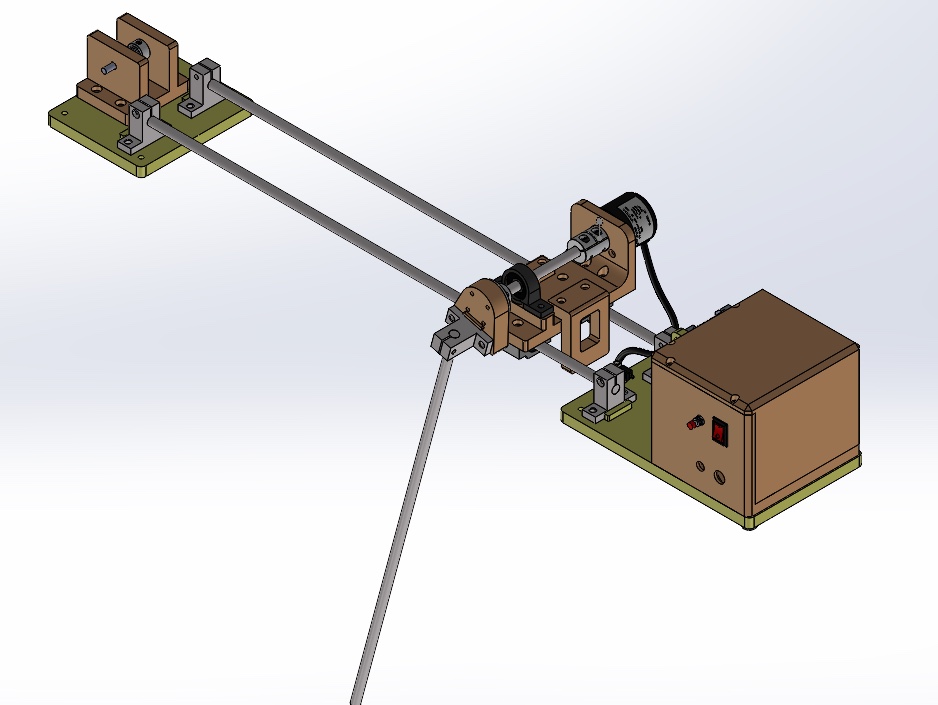
Build
Electronics box
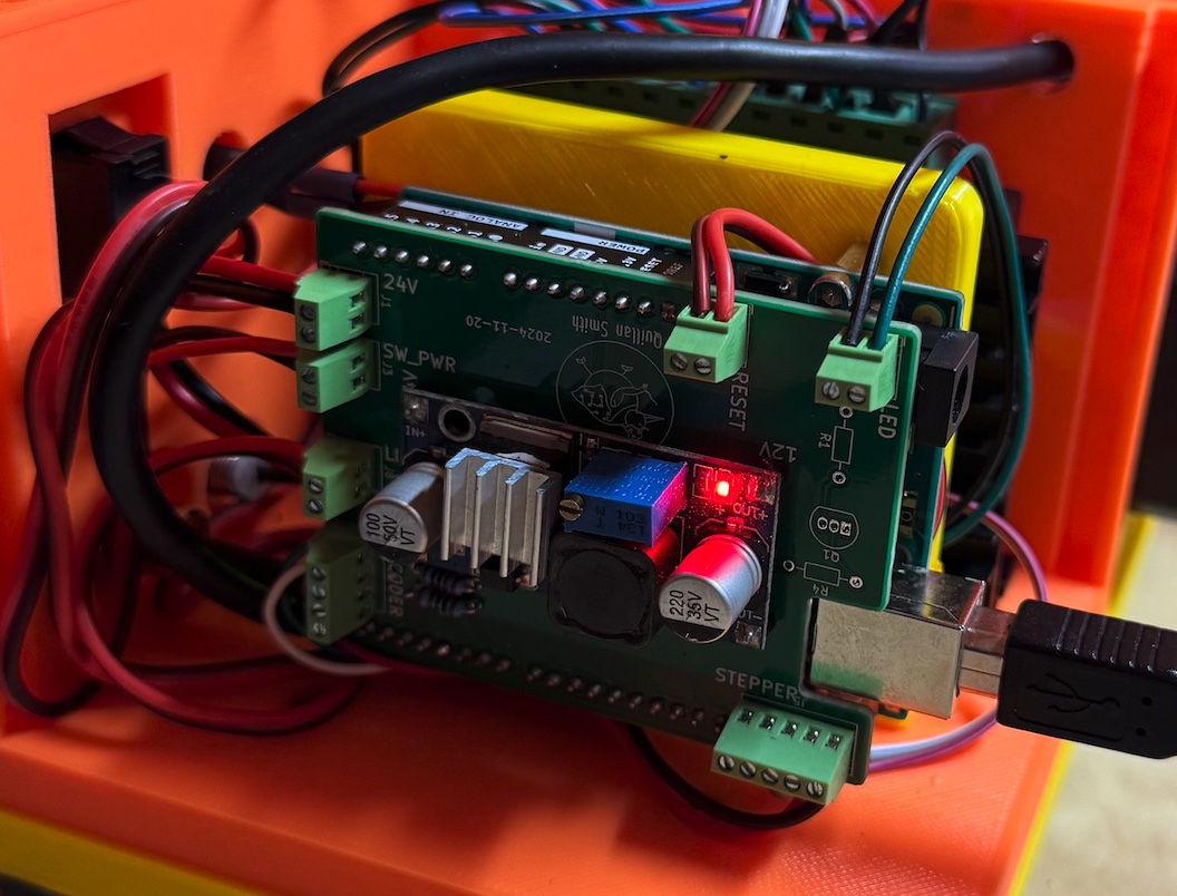
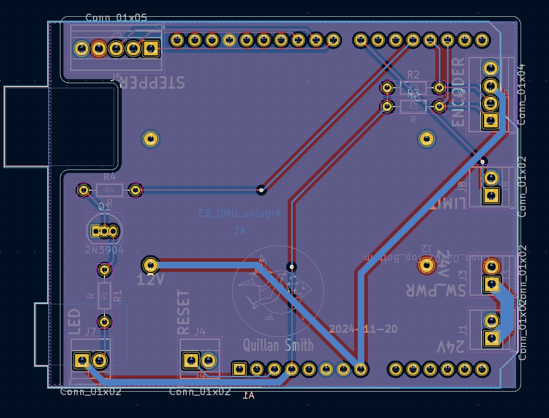
Houses the stepper motor controller and the Arduino UNO, along with a custom breakout board for clean connections to each component.
Carriage